Your shopping cart is empty!
Categories
- Batteries
-
Capacitors
+-
- Non Polarized +-
- Polarized +-
- SMD Capacitors Case A
- SMD Capacitors Case B
- SMD Capacitors Case C
- SMD Capacitors Case D
- SMD Multilayer Ceramic Capacitors 0402 (1005 Metric)
- SMD Multilayer Ceramic Capacitors 0603 (1608 Metric)
- SMD Multilayer Ceramic Capacitors 0805 (2012 Metric)
- SMD Multilayer Ceramic Capacitors 1206 (3216 Metric)
- SMD Multilayer Ceramic Capacitors 1210 (3225 Metric)
- Tantalum Capacitor
- Trimmer Capacitors
- Car Accessories +-
-
Connectors
+-
- Ethernet Cables And Connectors
- Audio Mono and Stereo Connectors
- Banana Connectors
- Barrier Terminal Block
- BLOCK Connectors PCB Type
- Cannon Connectors
- Coaxial Connectors
- Coaxial Connectors (SMA-SMB-SMC)
- Crimp Terminal Connectors
- Crimp Terminal Connectors Ring Type
- Crocodile Connectors
- D-SUB Connectors
- DC Connectors
- Dupont TJC Connectors
- IDC Connectors 2.0mm Pitch
- IDC Connectors 2.54mm Pitch
- Nylon Insulated Cord End Terminals
- USB Connectors
- Wire to Board Connectors
- Wire to Wire Connectors
- Wire to Wire SM Connectors
- Cooling Fans
- Crystal Oscillators
- Diodes +-
- Electronics Project Boxes
- Fuses and Breaker +-
- Gadgets and Gifts +-
- Heat Shrink Sleeves
- Heat Sink
- IC Base and Headers +-
- ICs +-
- Inductors +-
- Kits +-
- Knobs
- LCDs
- LIGHTS +-
- Magnets
- MicroControllers +-
- Motors +-
- PCBs +-
-
Potentiometers
+-
- Gear Tuning Potentiometer
- SMD Tuning Potentiometer
- 3006P Multiturn Precision Potentiometer
- 3296 Multiturn Precision Potentiometer
- 3362 Trimming Potentiometer
- 3386 Trimming Potentiometer
- WH06-1
- 3590 Wirewound Potentiometer
- WH06-2
- WH112A-2
- Knob Big
- WH148-1A
- WH148-1B
- Semi-Fixed (SR083)
- WTH118-1A Wire Wound
- Slide Potentiometers
- Shaft
- Trimmer Resistors
- WF-905CL
- Power Supply +-
- Relays +-
-
Resistors
+-
- SMD Resistors 0402 1005 Metric .06W 5%
- SMD Resistors 0603 0201 Metric .1W 1%
- SMD Resistors 0603 0201 Metric .1W 5%
- SMD Resistors 0805 2012 Metric .125W 1%
- SMD Resistors 0805 2012 Metric .125W 5%
- SMD Resistors 1206 3216 Metric .25W 5%
- SMD Resistors 2010 5025 Metric .75W 1%
- SMD Resistors 2512 6332 Metric 1W 5%
- 1/8W (+-0.1%) Carbon Film Fixed Resistor
- 1/8W (+- 1%) Carbon Film Fixed Resistor
- 1/8W (+- 5%) Carbon Film Fixed Resistor
- .25w (+-1%) Carbon Film Fixed Resistor
- .25w (+-5%) Carbon Film Fixed Resistor
- 1/2W (+- 5%) Carbon Film Fixed Resistor
- 1W (+- 5%) Carbon Film Fixed Resistor
- 2W (+- 5%) Carbon Film Fixed Resistor
- 5W (+- 5%) Fix Wirewound Cement Resistor
- 10W (+- 5%) Fix Wirewound Cement Resistor
- DIP Resistor Network
- SIP Resistor Network
- Rezonators
- Sensors +-
- Smart Boards +-
- Speakers and Buzzers
- Switches +-
- Thermistors +-
- Tools +-
- Transistors +-
- Varistors
- Voltage Regulators +-
- Wires and Cables +-
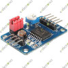
PCF8591 AD/DA Analog To Digital Converter Module
Buy Electronics parts through EVE-eVision Electronics Pakistan, Pakistan's first online electronics store.
Brand: Unbranded
Rs. SKU: 6024
Availability: In Stock
InStock
Rs. SKU: 6024
Availability: In Stock
Rs.900.0
AD/DA Converter Module Analog To Digital Conversion For Arduino PCF8591
Specifications:
-
PCF8591 key performance indicators:
- Single-Supply Operation
- PCF8591 operating voltage range of 2.5V to 6V
- Low standby current
- through the I2C bus serial input / output
- PCF8591 by 3 hardware address pins addressing
- Sampling rate PCF8591 I2C bus rate decided
- 4 analog inputs programmable as single-ended or differential inputs
- Automatic incremental channel selection
- PCF8591 analog voltage range from VSS to VDD
- PCF8591 built-in track and hold circuit
- 8-bit successive approximation A / D converter
- through an analog output DAC gain
Description:1. A module chip using PCF89512. module supports external voltage input capture (input voltage range 0-5v)3. Three modules integrated photoresistor acquisition environment through the AD intensity accurate numerical4. modules integrated thermistor, can capture the precise value of the ambient temperature through the AD5. The five-module integrated 1 channel 0-5V voltage input acquisition (blue potentiometer to adjust the input voltage)6. modules with power indicator light (on the module after power indicator lights)7. modules with the DA output indicator light board DA output indicator module DA output interface voltage reaches a certain value, the voltage the greater the light brightness is more obvious;8. module PCB size: 3.6cm * 2.3cm9. standard double-sided, plate thickness 1.6mm, the layout is nice, surrounded by the through-hole, aperture: 3mm, convenient fixed
Module interface:
The module's left and right, respectively, the external expansion of 2-way pin interface, respectively, as follows:Output interface of the left the AOUT chip DAThe AINO chip analog input interface.AIN1 chip analog input interfaceAIN2 chip analog input interfaceAIN3 chip analog input interfaceThe right side of the SCL IIC clock interface to access the microcontroller IO portThe SDA IIC digital interface connected microcontroller IO portGND module to an externalVCC power supply interface external 3.3v-5vModule red jumper instructions for useModule three red short circuit cap, respectively, the role are as follows:P4 connected to the P4 jumper, select thermistor access circuitP5 connected to P5 jumper to select the photoresistor access circuitP6 connected to the P6 jumper, to select 0-5V adjustable voltage access circuit
Buy Electronics parts through EVE-eVision Electronics Pakistan, Pakistan's first online electronics store.


